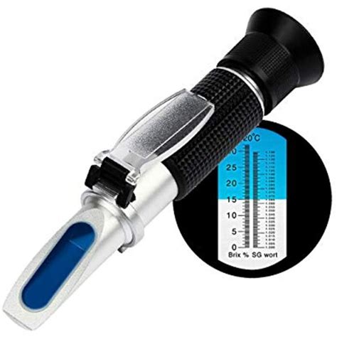
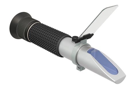
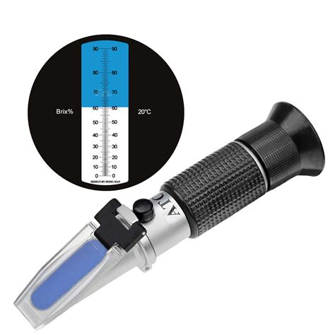
a schematic diagram of a typical refractometer|what is refractometer used for : solution Refractive index can be measured by the refractometer. We will use the double prism system called the Abbe's refractometer, shown in Figure 2. Figure 2 The schematic of the Abbe's . web4 de out. de 2023 · Express Rip is one of the most powerful tools out there for extracting content from audio CDs on your PC. You can extract audio .
{plog:ftitle_list}
In this crazy ADULT TIME DRIPPING CREAMPIE COMPILATION you'll see girls getting anal pounded and FILLED with cum! Guys eating their huge creampies and swapping it .
A refractometer consists of a light source, filtered to a single wavelength, which is directed towards the prism-sample interface by a converging lens. This creates a range of incidence angles, some of which (those less than the critical angle) . The Abbe instrument is the most convenient and widely used refractometer, Fig(1) shows a schematic diagram of its optical system. The sample is contained as a thin layer .
The LEICA ABBE MARK II Refractometer is a durable bench-top instrument. It provides efficient, reliable and repeatable readings in three modes: • % Solids (OBrix) • % Solids (OBrix) .

Refractive index can be measured by the refractometer. We will use the double prism system called the Abbe's refractometer, shown in Figure 2. Figure 2 The schematic of the Abbe's .We derive an optical model for the light intensity distribution around the critical angle in a standard Abbe refractometer when used on absorbing homogenous fluids. The model is developed using.
HOW IT WORKS. The phenomenon by which the direction of the light is modified after passing through an optic medium is called the refraction. It comes from a change of propagation . The ratio of the speed of light in a vacuum to the speed of light in another substance is defined as the index of refraction (aka refractive index or n) for the substance. Figure 1. Light crossing from any transparent medium into .
what is refractometer used for
The Refractometer Tutorial is an interactive animation that previews the use of the Bausch & Lomb Abbe Refractometer. Nine "procedure" steps are introduced to cover the operation, use .

Abbe's refractometer is used to measure the refractive index of the given organic liquid. Using a particular monochromatic light source, the apparatus is calibrated with water as the liquid. .The idea of schematic diagrams came into existence somewhere in 1300 A.D. when the first-ever geographical map, which is now known as Atlas, was drawn. Later, the same concept was used to draw the maps of stars and .
Piping and Instrumentation Diagrams (P&IDs) use specific symbols to show the connectivity of equipment, sensors, and valves in a control system. . and controllers and may be apparent in most, if not all, system .
Figure 4: Schematic (a) and the correspondent layout (b) of a filter designed using KiCAD . Although very different, schematics and layout are intimately connected: the schematics are used in design tools to generate a .
what does a refractometer mean
The basic language of control is the circuit diagram. Consist-ing of a series of symbols interconnected by lines to indicate the flow of current to the various components, it tells in . shows a typical line or schematic diagram. L3 Figure 2. Typical Line or Schematic Diagram T3 95 Reset 96 L2 T2 L1 1 3 2 T1 97 98 3 2 1 M OL 3-Phase Motor .
Download scientific diagram | Schematic diagram of the refractometer. from publication: The Influence of Dissolved Organic Matter to the Seawater Refractive Index Using Optical Refractometer .Schematic diagram of a coupler used as a refractometer. Light shone into one fiber enters the 1-cm-long, 30-m-radius fused section in the center and couples into the two output fibers in a ratio .
It is important to familiarize oneself with these symbols to understand the circuit diagram. The symbols provide valuable information about the type and function of each component. Circuit Flow and Pathways: Electrical diagrams also show the flow of electricity through the circuit and the pathways it takes. This includes information about the .These symbols represent various components, devices, and connections in a schematic diagram, allowing engineers and technicians to design, troubleshoot, and repair electrical equipment effectively. One of the fundamental advanced wiring schematic symbols is the resistor. It is a passive two-terminal electrical component that opposes the flow of .
Flowchart Maker and Online Diagram Software. draw.io is free online diagram software. You can use it as a flowchart maker, network diagram software, to create UML online, as an ER diagram tool, to design database schema, to build BPMN online, as a circuit diagram maker, and more. draw.io can import .vsdx, Gliffy™ and Lucidchart™ files .A typical disk centrifuge stack contains 100 or more disks. The disks reduce the distance that a solid particle must travel before it is separated from the feed. Disk centrifuges range in diameter from 102-762 mm, and are capable of creating forces up to 14,000 times that of gravity. The two diagrams below show how disk centrifuges work.
Download scientific diagram | Figure: The schematic of Abbe's refractometer According to the Snell's law, the refraction of this ray is then described by the maximum angle of refraction max. All .By learning these symbols, beginners can quickly identify and interpret the different components present in a circuit diagram. Connections and Wiring: Another important aspect of electrical schematics is understanding how different components are connected within a circuit. Schematics use lines and arrows to represent these connections, showing .Schematic diagram of the spatially resolved refractometer. It is a three-channel Maxwellian view system (see text), which has separate channels for the test, the fixation stimulus, and pupil .Download scientific diagram | Schematic view of the refractometer. from publication: A simple method to measure critical angles for high-sensitivity differential refractometry | A total internal .
refractometers are used to measure
This is where residential plumbing diagrams come in handy. These diagrams provide a visual representation of the plumbing system, showing the layout and connections of the various pipes and fixtures. A typical residential plumbing .Fundamental measurement principle of TFBG-based refractometry. (a) Schematic diagram of TFBG with surrounding liquid medium. The incident core mode is coupled into a reflected guided cladding mode .

The components in a circuit diagram are arranged and drawn in such a manner as to help us understand how the circuit works! As such, circuit diagrams are under no obligation to reflect how the circuit appears in real life! 2: Layout diagrams; Like circuit diagrams, layout diagrams use outlines of the shapes of the components of a circuit. The diagram below shows the actual pin arrangement of the 555 timer with the internal schematic diagram of the IC: The second image is the schematic symbol of the 555 timer used in diagrams: Operational Amplifiers. Operational amplifiers are voltage amplifiers with inputs and usually one output. They are also referred to as op-amps. A solar panel wiring diagram (also known as a solar panel schematic) is a technical sketch detailing what equipment you need for a solar system as well as how everything should connect together. There’s no such thing as a single correct diagram — several wiring configurations can produce the same result. P&ID symbols refer to the standard notations and graphical representations used on Piping and Instrumentation Diagrams (P&IDs) to depict the components and systems involved in process flows within a facility. These symbols are essential for engineers, operators, and workers to understand the layout, operation, and interconnections of the piping .
Circuit Diagram is a free application for making electronic circuit diagrams and exporting them as images. Design circuits online in your browser or using the desktop application.D 1000(f2 2 - f32) Results (12) The actual clinical evaluation of the instrument has been reported by many . This refractometer was modified so that it could be used in a natural viewing condition. With this design, the instrument myopia could be eliminated. . Refractometer FAQs What is a Refractometer? A refractometer is a simple instrument used for measuring concentrations of aqueous solutions such as gases, liquids, and translucent solids. Different types of refractometers are available depending on the application. Refractometers can be handheld, compact, benchtop, Abbe, and Brix as well as different .Diagramming Build diagrams of all kinds from flowcharts to floor plans with intuitive tools and templates. Whiteboarding Collaborate with your team on a seamless workspace no matter where they are. Data Generate diagrams from data and add data to shapes to enhance your existing visuals. Enterprise Friendly Easy to administer and license your entire organization.
wood floor moisture meter lowes
Download scientific diagram | Schematic diagram of refractometer based on NCF and SMS structure. from publication: Wavelength Dependence of the Sensitivity of All-Fiber Refractometers Based on the .In this diagram, beam A strikes the interface of medium 1 (with refractive index = n1) and medium 2 (with refractive index = n2, where n2 > n1) at the incident angle α1. . Figure 7 shows a schematic setup of a refractometer. To learn more about the measuring principle of refractometers, watch this video:
Wiring diagrams can also represent how electricity flows in a circuit. These diagrams show the power source and voltage, as well as the loads (lights and equipment) and any components that affect the flow of electricity, like switches. This type, called a schematic, is most often used by engineers and other electrical professionals.
wood floor moisture meter reviews
webPorque sos mi perdición Cuando haces tu aparición Es mi torpe corazón No hay más palabras Porque nublas mi razón En mi mente un apagón Y en mi torpe corazón No hay .
a schematic diagram of a typical refractometer|what is refractometer used for