maximum deflection of the beam compressive test 3 point bend|3 point bending equation : online sales In a three-point bending experiment, the beam is placed on two roller supports while an upper loading roller applies the bending load F. For a brittle material, we expect a monotonic . R$10 OFF. Use cupom Drogasil e ganhe R$10 OFF em suas compras. + 0,5% de cashback. Válido para compras no site. Aproveite! Verificado 4 .
{plog:ftitle_list}
WEBAssista a séries online grátis de maneira rápida, fácil e versátil. Clique no nosso site e veja nossas series grátis.
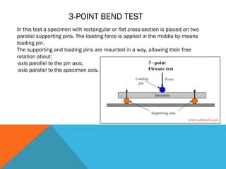
The three-point flexural test measures the flexural properties of materials by applying a load at the midpoint of a supported beam, providing insights into flexural strength, stiffness, and deformation resistance.
The three point bend test (Figure 1) is a classical experiment in mechanics, used to measure the Young’s modulus of a material in the shape of a beam. The beam, of length L, rests on two .the maximum bending stresses and deflection when the length-to-depth ratio is 20 or greater. Failure initiates on the tensile side when the material's compressive strength is equal to or .
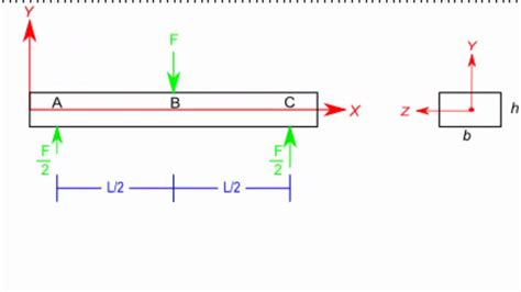
In a three-point bending experiment, the beam is placed on two roller supports while an upper loading roller applies the bending load F. For a brittle material, we expect a monotonic .Instead, a 3 point bending test is often used. Find an expression for the stiffness and deflection at the midpoint of the material, given the geometry, applied load , Assuming failure occurs at a .The three-point bending flexural test provides values for the modulus of elasticity in bending, flexural stress, flexural strain and the flexural stress–strain response of the material. This test .As seen in Fig 3, the beam undergoes deflection due to the bending action of the load ‘w’ on the beam. This bending of the beam develops tensile stresses on the outer edge of the deflected beam and compressive stresses on the inner .
The deflection is zero at the left end, so \(c_4 = 0\). Rearranging, the beam deflection is given by \[v = \dfrac{P}{48EI} [4x^3 - 3L^2x - 8 \langle x - \dfrac{L}{2} \rangle^3]\] The maximum deflection occurs at \(x = L/2\), which we can .The specimen used for the three-point bending test is a beam similar to the one sketched in Figure 3. The use of a span much larger than the cross-sectional height is intended to mitigate the effects of shear deformation and to replicate the assumptions of the Euler-Bernoulli beam theory. In a three-pointσ = 3 F L 2 b d 2. for a three-point bending test, where: F is the maximum load applied (N) L is the support span length (mm) b is the width of the specimen (mm) d is the depth of the specimen (mm) Flexural Modulus (Modulus of Elasticity) .
mobile automation testing white papers

The 3-point bend tests specified in ISO 178 and ASTM D790, describe classic standardized characterization methods for rigid and semi-rigid plastics.The flexural properties determined with these tests are of great importance to .The (three) 3-point bend test is conducted on flexural members of the structure such as the beam. . As seen in Fig 3, the beam undergoes deflection due to the bending action of the load ‘w’ on the beam. This bending of the beam develops tensile stresses on the outer edge of the deflected beam and compressive stresses on the inner edge of .
Show that, for the end loaded beam, of length L, simply supported at the left end and at a point L/4 out from there, the tip deflection under the load P is PL3 given by ∆= (316 ⁄ )⋅-----EI P A B C L/4 L The first thing we must do is determine the bending moment distribution as a .
We will show, for instance, that the deflection at the midpoint of a beam subjected to "three-point bending" (beam loaded at its center and simply supported at its edges) is . {48EI} [4x^3 - 3L^2x - 8 \langle x - \dfrac{L}{2} \rangle^3]\] The maximum deflection occurs at \(x = L/2\), which we can evaluate just before the singularity term .The 3-point bending test, also known as flexural testing or transverse beam testing, measures the . Record the weight and resulting deflection by the sample. 3. Repeat for different materials, keeping the weight constant. . Maximum Weight Test – fracture behaviour of materials 1. Use the same sample set up as the previous. 2. Continue .deflection w0 and the applied force P, and knowing the geometry of the beam and the experimental apparatus, it is possible to calculate the Young’s modulus of the material. 1Test methods according to ASTM D790 and their influence on the test speed: For materials that break at small deflections, the preference is to use a strain rate of 0.01 min-1 according to method A.; Materials that neither break nor show a yield point up to an elongation of 5 % are tested according to method B with a ten times higher strain rate of 0.1 min-1.
3 point bending test pdf
ASTM D790 measures the flexural properties of a material while under a bending strain or deflection. This test is conducted on a universal testing system using a three-point bend fixture at a rate proportional to the depth of the specimen. ASTM D790 testing is used to determine the following mechanical properties:Besides deflection, the beam equation describes forces and moments and can thus be used to describe stresses. . and the maximum compressive stress is at the location = . The three-point bending test is a classical experiment in mechanics. It represents the case of a beam resting on two roller supports and subjected to a concentrated load .Wood and composites are most commonly tested with the 4-point bend test. The 4-point test requires a deflectometer to accurately measure specimen deflection at the center of the support span. Test results include flexural strength and flexural modulus. Brittle Materials. When a 3-point bend test is done on a brittle material like ceramic or .
a simple beam with overhang. A beam with more than simple supports is a continuous beam. Figures 3.2a, 3.2b, and 3.2c show respectively, a simple beam, a beam with overhang, and a continuous beam. A cantilever beam is one in which one end is built into a wall or other support so that the built-in end cannot move transversely or rotate. TheThe flexural strength is stress at failure in bending. It is equal to or slightly larger than the failure stress in tension. Flexural strength, also known as modulus of rupture, or bend strength, or transverse rupture strength is a material property, defined as the stress in a material just before it yields in a flexure test. [1] The transverse bending test is most frequently employed, in . No headers. Bending moments are produced by transverse loads applied to beams. The simplest case is the cantilever beam , widely encountered in balconies, aircraft wings, diving boards etc.The bending .
Elastic modulus in bending (i.e., flexural modulus), stress-strain behavior, and failure limits in bending all can be obtained using the simple sample geometry of a 3-point bend test. ASTM D790 or ISO 178 covers flexural properties for . In a 3-point bending flexural test, a standardized specimen is bent under uniaxial bending stress until plastic deformation or fracture occurs. In this way, .
Place the test bar on the 3 point bend fixture and begin the test and end after bending to 5% deflection or until the sample breaks. Tips: Testing speed: The speed of the test is very slow and variable depending on the support span and depth of beam which are used in the calculation used to determine the speed.
The four-point flexural test provides values for the modulus of elasticity in bending, flexural stress, flexural strain and the flexural stress-strain response of the material. This test is very similar to the three-point bending flexural test.The major difference being that with the addition of a fourth bearing the portion of the beam between the two loading points is put under .of shear, moment and deflection at points along a beam. Cases can be superposed or overlaid to obtain combined values at some point on the beam. To find the point of combined maximum deflection, the derivative of the combined deflection equation can be solved for 0. This gives the point with slope = 0 which is a max/min on the deflection curve.6. Calculate the maximum deflection of a simply supported beam if the maximum slope at A is 0.0075 radians and the distance of centre of gravity of bending moment diagram to support A is 1.33 metres. a) 9.975 mm b) 9.5 mm c) 9.25 mm d) 9.785 mm View Answer
model question paper solved black box white box testing

Consider the simply supported beam in Fig. 1 below. The beam is subject to two point loads and a uniformly distributed load. Our task is to determine the mid-span deflection and the maximum deflection. Note that because the beam isn’t symmetrically loaded, the maximum deflection need not occur at the mid-span location.The maximum load exerted during the bending test is called breaking force. During the test, the values of the bending force and deflection are recorded. The material characteristics are then determined. . The 3-point bending test bears this name because there are three pressure points in this test setup: Two supports and a centrally loaded .They increase in magnitude linearly with \(y\), much as the shear strains increased linearly with \(r\) in a torsionally loaded circular shaft. The quantity \(v_{,xx} \equiv d^2v/dx^2\) is the spatial rate of change of the slope of the beam deflection curve, the "slope of the slope." This is called the curvature of the beam. 3.Find the maximum deflection magnitude and location. d) Determine the location and magnitude of the maximum stress in the beam. Problem 5-1 Solution: (a) Boundary conditions . ww (0) (l) 0. ww '(0) '(l) 0 (b) Find the deflected shape use direct integration We use the 4. th. order differentiated equation: EIw. IV. q. Integrate 3 times . 32 '0 ql .
This page titled 7.8: Plastic deformation during beam bending is shared under a CC BY-NC-SA 2.0 license and was authored, remixed, and/or curated by Dissemination of IT for the Promotion of Materials Science (DoITPoMS) via source content that was edited to the style and standards of the LibreTexts platform.Example - Beam with Uniform Load, Imperial Units. The maximum stress in a "W 12 x 35" Steel Wide Flange beam , 100 inches long, moment of inertia 285 in 4, modulus of elasticity 29000000 psi , with uniform load 100 lb/in can be calculated as. σ max = y max q L 2 / (8 I) = (6.25 in) (100 lb/in) (100 in) 2 / (8 (285 in 4)) = 2741 (lb/in 2, psi) The maximum deflection can be .
3 point bending strength
3 point bending span chart
3 point bending experiment
Resultado da Aquétipo Da Cleópatra PDF - PDF - Amor - Arquétipo | PDF | Arquétipo | Amor. O Scribd é o maior site social de leitura e publicação do mundo.
maximum deflection of the beam compressive test 3 point bend|3 point bending equation